![[JHG]](JHGlogo.png "Howard Gibson") More on 3D Printing
More on 3D Printing
More on 3D Printing
More on 3D Printing
See 3D Printing.
 I now have a 3D printer,
a Creality
Ender 3 Max.
This is capable of printing a 300mm (12in) cube.
My slicer is
Cura,
by Ultimaker,
which is available for
GNU/Linux.
It is really nice of Ultimaker to support other 3D printers
and GNU/Linux.
My only problem so far is that it recognizes my printer as a
Creality Ender 3, which prints only a 200mm (8in) cube.
The software lets me reset the size.
I now have a 3D printer,
a Creality
Ender 3 Max.
This is capable of printing a 300mm (12in) cube.
My slicer is
Cura,
by Ultimaker,
which is available for
GNU/Linux.
It is really nice of Ultimaker to support other 3D printers
and GNU/Linux.
My only problem so far is that it recognizes my printer as a
Creality Ender 3, which prints only a 200mm (8in) cube.
The software lets me reset the size.
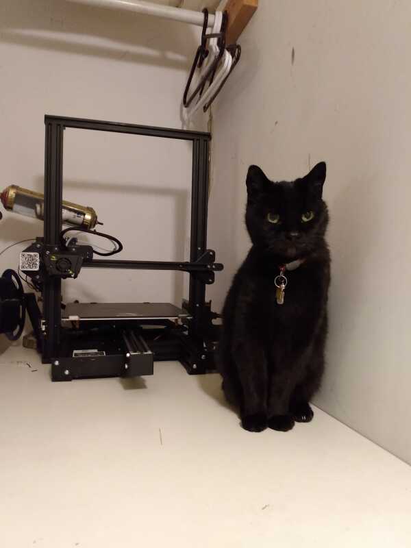
Make sure your 3D printer matches your cat!
This printer supports one filament spool only. There is no support for multiple colours, or for wash-away support material. As you can see from the picture, it is an open frame, vulnerable to inquisitive cats. I may have to make a Plexiglas enclosure for it, but so far, my cats are ignoring it.
I had no serious problems assembling this thing. The instructions have a Chinglish feel to them, but things were clear enough to me. I am a mechanical engineering technologist, with three year diploma, and forty years of work experience. I am not fabulously handy, but maybe you will need help! My package came with tools, and a lot of spare parts, including preload springs and nozzles. I did have to locate and reset a switch in the power supply from 230VAC to 115VAC.
The Ender 3 Max is mostly a frame assembled from what appear to be standard aluminium frame extrusions. This definitely is not industrial design. This is not a problem, just an observation. 3D printing is new, bleeded edge technology. A whole bunch of manufacturers soon will be weeded out, very likely including Creality. This device uses standard filament spools, so you should be able to continue ordering these. I don't know how standard nozzles are.
You need to level
the platform.
I have sat this thing on a drafting board that was visibly out of level
and it worked fine.
What you need to do is manage the distance between the nozzle
and the platform.
The nozzle should be set 0.1mm above the platform.
This is .0039in for those of you with English micrometers,
about the thickness of a sheet of paper.
I have seen at least one YouTube video
claiming that a piece of paper is not a proper measuring device,
but it works fine for me.
My Mark I eyeball works fine too.

Preload Springs
When I level mine, I almost completely disenge the preload springs. I may investigate longer ones. The springs are fairly stiff, they are painted, and the coils are rectangular section. This is typical of the diesprings, used on stripper plates on progressive dies. These are available from industrial fastener suppliers, they are cheap and very stiff. The drawing to the right was printed 1:1, so the dimensions in millimetres give you a scale reference.
Levelling is not set-and-forget. I make a point of inspecting my printer before any serious job. Prints take quite a few hours. You don't want to mess up.
I am having quite a few problems with this printer. On a couple of occasions, my 3D model has unstuck from the bed, and the plastic has extruded itself all over the print head. I have to break the plastic off the head. Once, I managed the break off the thermocouple that monitors the temperature of the print nozzle. Thermocouples are only a couple of dollars each. The expensive part is the shipping or driving needed to get them. The connectors on the new thermocouple did not work, and I wound up cutting and resoldering the wires. The wire routing on the Ender 3 Max is a pain.
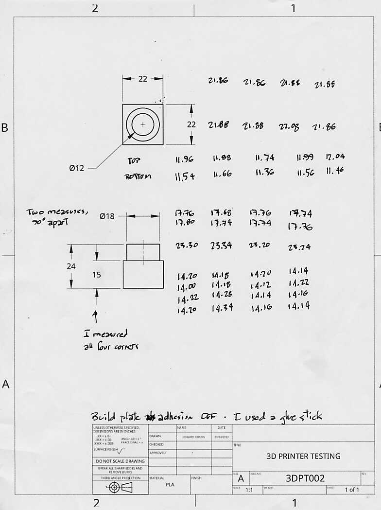
When you put out a contract to have someone fabricate something for you, you request a First Article Inspection report. Let's make up a part, and do an inspection.
I went on to OnShape
and I designed a test piece.
I saved the STEP file in Fine
resolution.
In my slicer Cura, I set...
Part Adhesion
The bottom faces were not flat
 Here are the results.
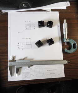
I printed four pieces.
I have a metric micrometer,
but my errors were large enough
to be easily measured by vernier calipers.
Here are the results.
I printed four pieces.
I have a metric micrometer,
but my errors were large enough
to be easily measured by vernier calipers.
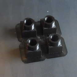
To the right, you can see the four pieces on the printer's platform.
The thin pad surrounding them was printed
because I turned on the Build plate adhesion
.
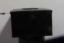
The bottoms of the parts came out warped,
as you can also see to the right.
I wonder if I would be better off using the glue-stick adhesive.
The parts were very easy to remove from the platform.
 Here are my actual results.
Click on drawing 3DPT002 to get a bigger image.
The 15mm measurement was tricky because of the curved bottoms,
and many of my numbers were over a millimetre below specification.
All of my external measurements were low.
My 12mm inside diameter were accurate at the top of the part.
At the bottom, they were low,
before and after I cleaned up the edges with a knife.
Here are my actual results.
Click on drawing 3DPT002 to get a bigger image.
The 15mm measurement was tricky because of the curved bottoms,
and many of my numbers were over a millimetre below specification.
All of my external measurements were low.
My 12mm inside diameter were accurate at the top of the part.
At the bottom, they were low,
before and after I cleaned up the edges with a knife.
I wonder how predicable this all is? If I can scale my 3D models to account for the errors, I can still 3D print accurate objects.
I re-printed my test parts with Build plate adhesion turned off. I used a glue stick to retain the parts. On the bottom faces, the flatness improved quite a bit. I did not see significant variation in results, otherwise.
In summary (so far), the Creality Ender 3 Max's FDM process is not super accurate. Outside and inside dimensions generally are less than the nominal sizes of the models. Continue using glue sticks to retain your part to the platforms.
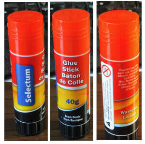
Bad Glue Stick!
It turns out there are glue sticks and there are glue sticks. I picked up the one to the left, at a dollar store. It probably is okay for glueing paper. The text on the glue stick does not mention 3D printing. Non‑toxic is good around small children. If you use it to retain your 3D print, it will peel off. I spent a week trashing 3D parts finding this out.
Search the internet for 3D printing glue sticks. Elmer's disappearing purple sticks are highly regarded, and they are working for me at the moment.
Gear trains are fun. I want to print some, but we need to understand and cope with the tolerances of 3D printing.
How to fake involutes
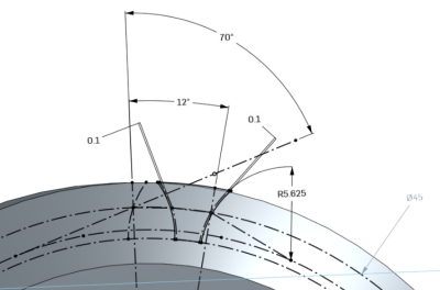
If you want to model gears, you should understand gear geometry, diametral pitch, metric modules, and how to work out the angles between gear teeth. The sketch to the left comes from Engineering Drawing Sixth Edition, by Thomas French. My copy is from 1946. Basically, if you draw the correct radius and put it in the correct place, you get something that looks like an involute gear. My 3D printed parts run smoothly, which is what involute gears are supposed to do. A similar method is shown in Dudley's Gear Handbook Second Edition, by Dennis P. Townsend. I have not tried it.
The figure shows an OnShape sketch of a gear tooth, or more precisely, everything but the gear tooth. The "correct" outlines of the gears are shown as phantom lines. The gear has a 20° pressure angle, thirty teeth, and is 1.5(mm) module.
| From figure | Actual Value |
|---|---|
| ⌀45 | pitch diameter of the gear |
| 12° | One thirtieth of the circumference |
| 70° | 90° minus the 20° pressure angle |
| R5.625 | 1/4 of the pitch radius |
| 0.1 | The clearance modelled into the gear teeth |
The 70° line picks up a tangent circle, which picks up the radius of the gear tooth faces.
The guys who cut metal gear teeth methodically cut the space slighly oversize. This ensures that the gear teeth mesh. On most gear drives, a little play in the gears is harmless.
On my first attempt to model and print an epicyclic gear drive, I failed miserably. I needed to build clearances into the design. My gear drives are built to metric 1.5 module, which is approximately 16DP. My shafts are 10 to 20mm. I have done some simple test drives with 0.15mm clearances around the shafts. I have modelled my gears each with 0.1mm clearance. This seems to run fine.
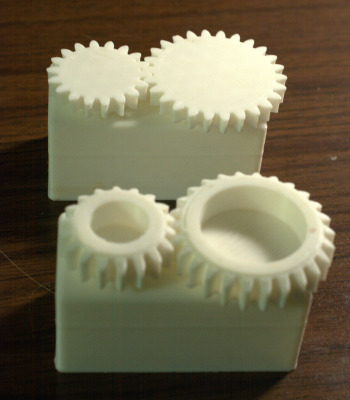
Printed Gears
Look closely at the printed gears to the right. All four gears were printed with the top faces rotated down onto the platform. The two gears on top have spread out a bit at what was the bottom printing face. The two gears at the bottom have 30° chamfers on that face. This seems to have worked at keeping a good gear profile all across the gear teeth.
English gears are sized by diametral pitch, DP. Metric gears are sized by module, m. The figure to the right shows the term pitch radius. In engineering, we normally work out diameters, like pitch diameters, DP. The number of gear teeth is N The pitch diameter of a gear is the nominal contact point between the gears.
Pitch diameter: DP = N×m (mm) = N÷DP (in)
The pressure angle is the angle of contact between the two gear teeth. On older English gears, 14.5° is common. On modern gears 20° is standard, or at least, very popular. The 70° line shown on the figure is 90°-20°.
Addendum = 1.00×m (mm) = 1.00÷DP (in)
Dedendum = 1.25×m (mm) = 1.25÷DP (in)
The outside diameter of a spur gear, as you should be able to see from the figure, is the pitch diameter plus two times the addendum.
3D Printing
Pinion Shaft
DFM stands for Design For Manufacture. An important part of designing anything is understanding how it will be manufactured.
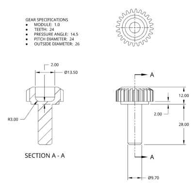
Pinion Shaft Drawing
The two primary problems with 3D printing are adhesion to the platform, and printing horizontal bottom faces.
You can manage adhesion quite a bit by applying adhesive to the platform, and by making sure the platform has been "levelled" as noted above.
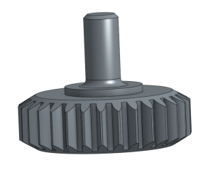
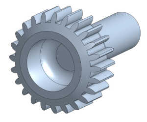
Different Gear Oriented For Printing
The figure to the right shows a different gear somewhat better designed for 3D printing. It is sitting in its as-printed orientation, with the shaft and its chamfer on top printed last. As noted above, I cannot print gears with an end in contact with the table. The bottom chamfer lifts the gear teeth above the table a bit. The second chamfer is just there to match the first one. I have found that a sharp corner between the shaft and the main gear body is weak. The 2mm fillet provides reasonable shaft strength. The shaft itself is reasonably strong. The problem is the discontinuity.
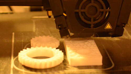
Horizontal Faces
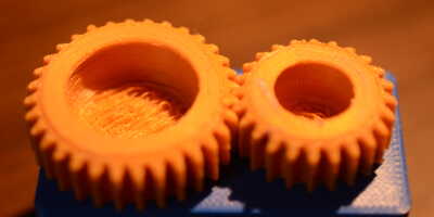
3D printing works by applying a bead of plastic layer by layer. This works very well at printing vertical features. It works fairly well with angled features like the chamfers on my two gears. It sucks at horizontal features lifted above the base. Look at the orange gears to the left. I am impressed that this worked at all!
The orange gears were designed with a metric module of 1mm. The module value controls the gear pitch. I could not get the gear teeth in focus. The gear teeth work, but they are very rough. 1.5(mm) module teeth look way better. I used a 0.4mm diameter nozzle on the printer. I have a 0.2mm diameter nozzle I have not yet tried.
Almost certainly.
My cat Chico
![]() Howard Gibson —
Email
hgibson@eol.ca
—
Last updated:
2024-04-27
Howard Gibson —
Email
hgibson@eol.ca
—
Last updated:
2024-04-27