![[JHG]](../JHGlogo.png) Calculating Locational Tolerances
Calculating Locational Tolerances
2022/05/17
Calculating Locational Tolerances
Location tolerances are required to ensure that parts, and their fasteners, fit together and that features are located to within specification. What follows is a systematic procedure for determining locational tolerances for bolts, screws, pins, shafts, and features embedded on the parts. This document is intended as a guide for designers, drafters and drawing checkers.
The terminology used in this document will be familiar to anyone who has read up on or is trained in Geometric Dimensioning and Tolerancing (GD&T).
This document is copyright © 2022/05/17 by Howard Gibson. You may copy this document onto bulletin boards, web pages and other computer media, as long as the file is unaltered, and the distribution is not-for-profit. All other rights are reserved.
1998 Sep 14: First issue.
1998 Dec 01: Clarified some text. Expanded Positional Tolerances section a bit.
1999 Aug 24: Added a web page reference. Typo correction.
2000 Jul 20: Cleaned up the HTML formatting a bit. No change in text.
2000 Aug 27: Clean up HTML some more, finally getting background colour to work. Maximum error for datum dimensioning as 45∘ opposite to each other. The section of precise geometric tolerancing made a little clearer.
2005 Jul 20: Rewrote GD&T section.
2006 Apr 29: Reformatted LaTeX code. No change to content.
2007 Oct 31: Deleted section Zero Tolerance Applied Without MMC
2010 Jun 01: Added Implied 90∘ subsection. Moved the zero positional tolerance section to the Appendix, and wrote the Positional Tolerance from First Principles section.
2010 Jun 02: A couple of minor corrections.
2014 Jul 04: Corrected Figure 5
2015 Jan 02: Corrected Figure 6 and Figure 7 Finally ran spellcheck. Only two corrections! :)
2016 Apr 23: Fixed four bolt pattern equation. Clarified equations for Datum Dimensioning. Added a figure for Datum Patterns.
2020 Mar 11: In ASME Y14.5M-1994 Appendix B notes, I swapped H and F into the correct positions. I updated LaTeX code a bit. I clarified my notes on pitch circles. Thank you John Olson and Edward Alexander.
2020 Mar 19: Added separate section on pitch circle radii. Changed MMC to MMB as per ASME Y14.5-2009. Moved elaborate pitch circle model to appendix.
2020 Apr 27: Tidied up and clarified Figure 11. Clarified Screw From First Principles a bit.
2021 Mar 27: Fixed typos under radial pitch circles. Fixed some issues due to LaTeX updates.
2021 Sep 14: Fixed error in Four Fastener Pattern. Thank you Chris Thomas.
2022 May 07: Added Design of Holes With GD&T.
2022 May 10: Improved equations of Design of Holes with GD&T.
2022 May 17: Removed editing mark.
When parts are held together by more than one fastener, the tolerances for the holes must ensure not only that the parts are located to within specification, but also that all the fasteners can be installed. Analysis will consist of determining the maximum possible location error that will allow this, and then working out the equivalent drawing tolerance. It will be assumed that all holes are drilled, punched, tapped or whatever, prior to assembly. If the tolerances generated by the following calculations are not reasonable, drilling at assembly may be the only solution.
The analysis will cover a series of fastener configurations and dimensioning procedures. For the purposes of building analysis models, fastener assemblies can be split up into two categories, which will be termed here “bolts” and “screws.” For each of these, we can determine a maximum acceptable error, and for each design configuration, and for each style of tolerance application on the drawing, we can work out the tolerance.
Fasteners pass through clearance holes in both parts. The obvious example of this is a nut and bolt assembly, but this could also be a cotter pin assembly or a pre-drilled rivet assembly. The bolts could be clamping more than two parts at a time.
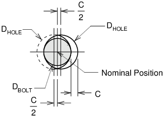
See Figure 1 . It will be assumed for analysis purposes, that bolts are located precisely at their nominal position.1 The two clearance holes are shifted off the nominal position such that their edges just touch the bolt on opposite sides. This is the maximum acceptable error condition. If the clearance in each hole at MMB is C, then…
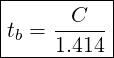
Maximum allowable shift of holes for bolting:
| (1) |
Fasteners pass through a clearance hole in one part, and are solidly located in the other part. These could be screws in tapped holes. They could be dowel pins, or they could be features integral to one of the parts. As with a bolted assembly, a screw could be holding more than one piece to its base.
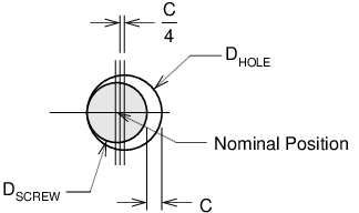
See Figure 2 . The screw and clearance hole have moved in opposite directions, such that the screw is touching the edge of the hole. If C is the clearance in each hole at MMB, then…
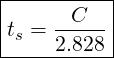
Maximum allowable shift of holes for screwing:
| (2) |
A screw assembly allows only half the error of a bolted assembly. This is something to consider if the location tolerances are difficult to maintain.
The ASME Y14.5 standard recommends the use of positional tolerances for locating features of size, with a secondary preference for profile tolerances. Much of this article looks at ± tolerances for locating holes. This was the original purpose of the article. People still use this notation for tolerances, and it is defined under the ASME standard, so as design checker, you can accept it if it works. If you are designing or drafting, you will see from this article that positional tolerances are the better way.
For two dimensional configurations, it will usually be assumed that the maximum error occurs at a 45∘ angle. The assumption is that the fabricator’s capability is equal in both the x and y directions. If this assumption is not true for a given application, then the angle, and the resultant calculations and tolerances can be fudged a bit, although not very much.
The tolerance that must be applied on a drawing feature depends on the configuration of the fasteners and on the dimensioning procedure. Most articles on ASME Y14.5 Dimensioning and Tolerancing point out that GD&T provides a maximum of allowance for a given part. This is important if the tolerance to be achieved is marginally within the fabricator’s capability., An increase in allowance May reduce costs. If tolerances are fairly easy, then the cost of preparing and reading the drawings must be considered. Regardless of how the tolerances are applied, GD&T provides a precise interpretation of how the tolerances are to be determined from the dimensions.
See Figure 3 . ASME Y14.5-2009 paragraph 2.1.1.32 states that undimensioned angles that appear to be 90∘ are to be assumed to be 90∘. The tolerance of an undimensioned orthogonal feature is the value specified on your default tolerance notes. On most drawings, this is something like ±0.5∘, or ±1∘.3
If holes are located from an edge with ± tolerances, consider the possibility that the edge is not perpendicular to the base. Do you measure from the straight line that contacts the two outsidepoints of the edge? Do you measure from the nearest part of the edge?
This is not an issue with GD&T positional tolerances, since everything is located from the orthogonal datums you specified. Using a profile tolerance to control the outline of your part is good practice.
If you are checking drawings prepared with ± tolerances, you will have to decide how willing you are to argue with the drafter or designer. A machine or sheet metal shop that wants repeat business is not going to deliver parts 1∘ out of perpendicular, even if the drawing allows it.
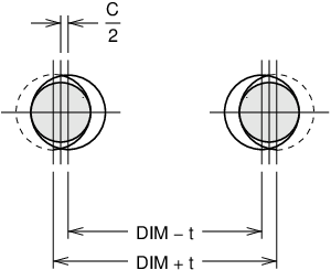
Parts are assembled with two fasteners. It is assumed that the parts are not located accurately to each other. On the drawings, the holes are dimensioned from each other, rather from a datum.
In Figure 4 , the maximum error occurs at both holes, so that tolerance is double the error…
Tolerances for dimensions between two bolts
| (3) |
For screws…
Tolerances for dimensions between two screws:
| (4) |
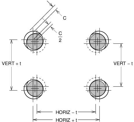
Parts are assembled with four fasteners. Again, the relative location of the clamped parts is not critical. On the drawing, the holes are dimensioned with respect to each other as shown in Figure 5 .
The holes in Figure 5 are shown shifted the maximum distance, at a 45∘ angle. Again, the error occurs at each hole.
The tolerance for dimensions between four bolts:
| (5) |
For screws…
The tolerance for dimensions between four screws:
| (6) |
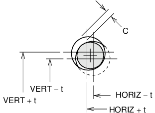
Parts are assembled with any number of fasteners. On the fabrication drawings, all the holes are dimensioned from arbitrarily selected X and Y datums.4 For one-off parts, this is popular with machine shops (and therefore cheaper) because only one set-up is required to locate all the holes. If the two parts are to be located accurately, all the holes must be registered to some locating features. On any non-rectangular hole pattern with more than two holes, the dimensioning effectively is datum, even if everything is referenced from one of the holes.
The model assumes that two holes are located from datums. Each hole can shift in two dimensions, even if the holes are arrayed in a single line. It is assumed that the maximum error occurs when both holes shift to the maximum allowed, in opposite directions.
The tolerance for a datum dimension to a bolt hole:
| (7) |
For screws…
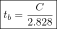
The tolerance for a datum dimension to a screw hole:
| (8) |
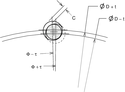
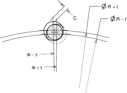
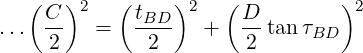
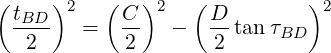
Fasteners are located at specified positions around a circle, as shown in Figure 7 . This model is similar to the datum dimensioning. Each fastener is located from a datum by two dimensions, typically, a diameter and some angles.
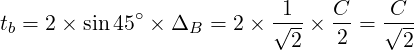
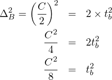
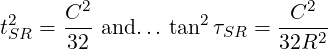
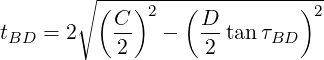
For a bolted assembly, the total error must not exceed ΔB. This error is a combination of t, τ, and D. Since the dimension tolerance t acts on the diameter, the effective allowance due to the specified t is t∕2…
The simplest solution to this is to assume that the maximum allowable error acts at a 45∘ angle from the radial. In this case, the effective diameter error equals the effective angular error…
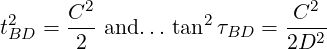
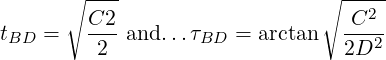
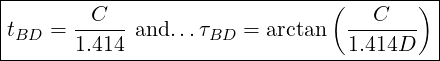
For a bolted assembly arranged on a pitch circle, the diameter and angular tolerances are…
| (9) |
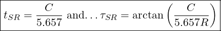
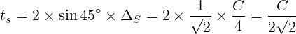
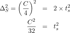
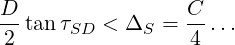
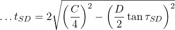
For a screwed assembly, the total error must not exceed ΔS…
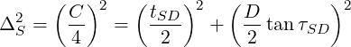
Again, we assume that the maximum allowable error occurs at 45∘.
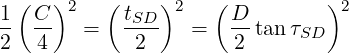
For a screwed assembly arranged on a pitch circle, the diameter and angular tolerances are…
| (10) |
In the above analysis, the angular tolerance must be tightened as the diameter increases. At some magnitude of diameter, this will be too tight for fabrication at an acceptable cost. There are several ways around this.
Do not specify pitch circles. Use datum dimensioning. Linear dimensions are not sensitive to increasing size. Fabricators often re-calculate pitch circles as datum dimensions anyway, since this is more suitable for their machinery. Datum dimensions are also easier to inspect.
Use GD&T positional tolerances.
Replace the holes with slots, with the long dimension arranged along the pitch circle. This is economical if the part is being punched.
Fudge the above calculations by opening up the angular tolerance a bit and closing the diametral tolerance to make up for it. This is worked out in Appendix B . It does not help much.
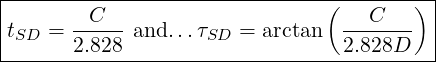
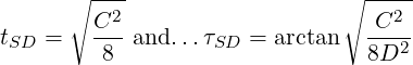
Sometimes, pitch circles are specified by radius, as per Figures 1-52 and 1-57 in ASME Y14.5-2009.5 It is not conveniently obvious how this works out.
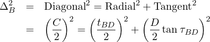
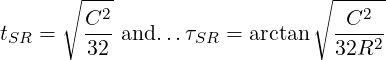
For a bolted assembly, the total error must not exceed ΔB. This error is a combination of t, τ, and R.
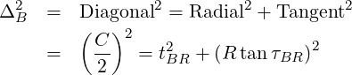
The maximum error is modeled at 45∘ angle from the radial.
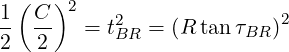
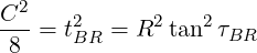
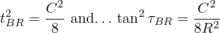
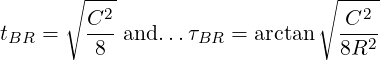
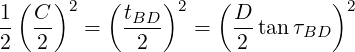
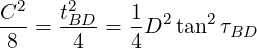
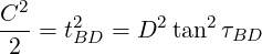
For a bolted assembly arranged on a pitch circle, the radial and angular tolerances are…
| (11) |
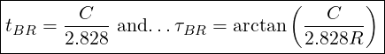
And for screws…
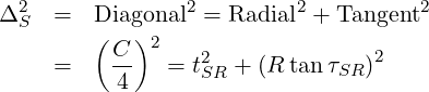
At 45deg from the radial…
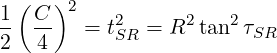
and…
For a screwed assembly arranged on a pitch circle, the radial and angular tolerances are…
| (12) |
The GD&T positional tolerance defines a tolerance zone within which the centre of the hole must be located. The hole is located with respect to one or more datums.
In most cases, this is exactly what you want to specify, so positional tolerances ought to be the preferred method.
There are several ways to apply tolerances to holes and to their positions.
See Figure 9 . GB is the positional tolerance to be called up on the drawing for a bolted assembly. C is the diametral clearance at MMB of the bolt and hole.
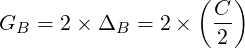
For a bolted assembly, the geometric tolerance is …
| (13) |
For a screwed assembly…
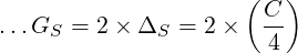
For a screwed assembly, the geometric tolerance is…
| (14) |
Let’s ignore the bolt and screw models preceding.
We want to install a fastener, and we want the clearance holes to clear it. In the following analyses, we assume that the parts are located by datums A, B and C which are external to the hole pattern.
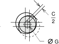
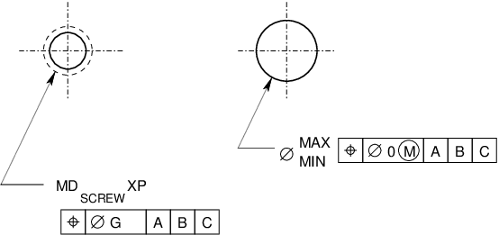
We locate our bolt at the exact nominal position, as shown in Figure 10 . Only one hole is shown. Presumably, the bolt clears at least one more hole, but they all work the same way.
Located exactly at nominal position, an infinitesimally larger clearance hole will clear the bolt. As the hole gets larger, it can shift some distance off nominal and still clear the bolt, as shown in Figure 10 . The geometric tolerance G applies to the hole, only.
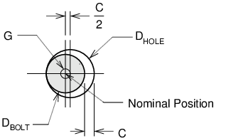
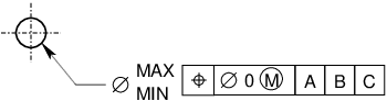
Figure 11 shows the dimension specification we want to use on each part that requires a clearance hole. The zero positional tolerance applies only at MMB, the minimum clearance diameter. In the LMB case, you have the maximum sized hole, shifted the maximum clearance off to one side. The maximum diameter allows for the off-centre error as well as the error in the hole diameter.
| (15) |
The hole must be larger than the bolt.
For our maximum diameter, we must allow for a reasonable positional tolerance G plus a reasonable fabrication tolerance on the hole diameter which would be ±tHOLE.
| (16) |
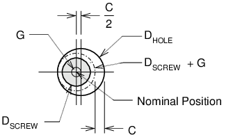
See Figure 12 . For simplicity, we assume that the positional tolerance G is the same for the tapped hole and the clearance hole.
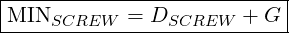
Our two parts require the dimension specifications as per Figure 13 .6 The tapped hole shown is metric, with a major diameter of DSCREW and a pitch P which is not used on these calculations.
The screw is potentially able to occupy a space of DSCREW + G, as shown on Figure 12 . The clearance hole must clear this.
| (17) |
The positional tolerance of the tapped hole controls from the part’s surface to the bottom of the tapped hole. Your clearance hole must clear whatever sticks out of the tapped hole. If your clearance hole goes through a thick plate, you should add a projected tolerance zone to your feature control frame, or at least, increase MINSCREW a bit.
Specifying MMB on a tapped hole makes no sense to me. Tapped holes are self-centreing, so there is no bonus tolerance!
For the clearance hole, again, we add a reasonable positional tolerance G, and the clearance hole tolerance ±tHOLE to get…
| (18) |
It is not necessary for the positional tolerance G to be identical for the tapped hole and the clearance hole. If the tapped hole is in a machined part and the clearance is in a sheet metal part or a weldment, an accurate GTAP will allow for a sloppier GCLEAR. Or, vice versa!7
If you are checking a drawing dimensioned like Figure 11 , you can verify that the tolerance is fabricatable.

Obviously, maximally tight values for G and ±tHOLE should not exceed the difference between MAX and MIN.
When you place a bolt or screw, the clearance holes must not intrude into any space that may be occupied by the fastener.
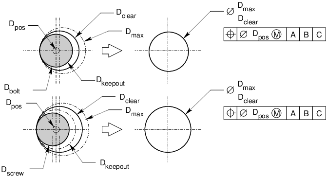
Figure 14 , shows a bolt and a screw with holes located to GD&T positional tolerances of Dpos. At MMC, our clearance holes are Dclear.
If the fastener is a bolt, it is centred on the nominal position, with zero positional error.
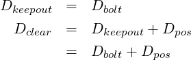
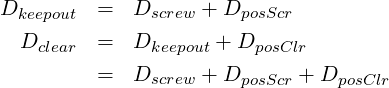
If the fastener is a screw, we need to add the positional tolerance of the tapped hole. The screw can move off centre and touch the edge of the keepout diameter. From Figure 14 , we can see…
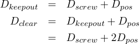
Note how Dkeepout is located precisely at nominal.
Dclear is the minimum diameter that will reliably clear your fastener at the given positional tolerance. The positional tolerances are shown called up at MMC, which allows for more positional error at LMC, as shown. It is apparent from Figure 14 that with a bolt, you either have smaller clearance holes, or looser positional tolerances.
Consider the possibility that one of your parts can be fabricated more accurately than the other. Perhaps you have a machined housing with tapped holes, sitting on top of a weldment. The machined tolerance is DposScr. The mating hole is DposClr.
Our bolt model does not provide an opportunity to tighten one tolerance and open up the other. See ASME Y14.5M-1994 Appendix B Example , below, for an example of a bolt not being located at nominal.
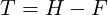
ASME Y14.5M-1994 proposes the fixed fastener case,equivalent to my bolts, and the floating fastener case, equivalent to my screws.
| D | = | minimum depth of thread or minimum thickness of part with restrained or fixed fastener |
| F | = | maximum diameter of fastener (MMB limit) |
| H | = | minimum diameter of clearance hole (MMB limit) |
| P | = | maximum thickness of part with clearance hole, or maximum projection of fastener, such as a stud. |
| T | = | positional tolerance diameter |
The floating fastener case…
or…
The fixed fastener case…
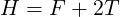
or…
An interesting problem came up on Eng-Tips forums, http://www.eng-tips.com.
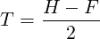
We are assembling two parts, one of which was designed and manufactured outside. We control the dimensions and tolerances only of the other part. The device is assembled using screws and nuts, so the floating fastener case applies. We can modify the equation for two sets of tolerances as follows…
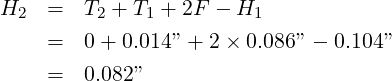
The manufactured part has a clearance hole H1 = 0.104” and they have specified an orthogonal tolerance of ±0.005”. This is equivalent to a geometric tolerance of T1 = 0.014”…
Let’s set T2 = 0, and solve for H2.
The calculated clearance hole is smaller than the screw!
Let’s try again, setting H2 = .086”, and solving for T2.
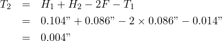
Now the result makes sense. If you provide a zero clearance hole, you may allow a 0.004” positional tolerance. This violates our standard model in which the bolt is located at the exact nominal position, but it is a perfectly functional assembly.
When you solve this problem, solve for the tolerance, not the hole diameter.
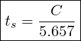
Take the case that we have a 1/4-20UNC screw, and a clearance hole of 9/32 DIA. Work out the tolerance for a datum dimension, and for a GD&T positional tolerance. Assume that the hole is drilled, and that it will be bigger than nominal.

Datum Tolerance: ts = C∕5.657 = .03125”∕5.657 = .0055” ≈ .005”
Positional Tolerance: GS = C∕2 = .03125”∕2 = .0156” ≈ .015”
Let us continue with the problem, this time assuming that the fabricator can locate holes to within a .010” diameter, and drill holes in to ±.005”. We will specify a positional tolerance of zero at MMB, and work out reasonable MAX and MIN diameters of the clearance hole.

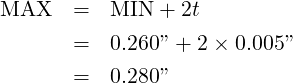
The 1/4-20UNC hole will be located to a positional tolerance of .010”. The clearance hole will be .280/.260”, located to zero at MMB.
One thing to consider when applying tolerances to fabrication drawings, is the actual capability of your fabricators. The author has inspected parts fabricated in a machine shop. The observed location errors for holes were typically within 0.003 in. (⊕ .006). This was close to the accuracy of the vernier equipment that was used, so a significant part of this was measurement error.
The author has not checked sheet metal, castings or weldments with similar thoroughness.
He has been told by a sheet metal fabricator, that sheet metal holes can be located to within .015” with respect to a folded edge. This fabricator is skilled, so other shops may not be as good.
Check out the D.S.M. Manufacturing Company’s web page for more sheet metal tolerances. For their sheet metal, they quote ±.003in for hole diameters, and ±.005in for hole to hole locations in parts that do not have too many holes punched in them. They would prefer it if designers allowed ±.010in. Hole to fold tolerances should be ±.015in, and fold to fold tolerances should be about ±.020in.
The D.S.M.’s web page is at…
http://www.precisionsheetmetal.com
One objective of toleranceing, particularly geometric toleranceing, is to control costs by allowing as much variance as possible. This can reduce scrap rates by increasing the probability that fabricated parts conform to specification. This might reduce fabrication costs by allowing the fabricator to work faster, or use a cheaper manufacturing process.
Another possibility is that the standard manufacturing process can easily achieve the specified tolerances. In this case, a complicated drawing may increase the cost as the fabricator takes the extra time required to interpret the dimensions, and for that matter, as the designer takes the extra time required to produce the drawing! This is particularly true for one-off items, and for items requiring complete inspection, and any other situation that imposes frequent reference to the fabrication drawings.
The designer must balance the cost of managing the drawings against the need for loose, easily met specifications.
The following sections were under GD&T Positional Tolerances in earlier versions of this document. These notes are correct, but not particularly readable. I think my current notes show a better system.
The hole specification shown in Figure 11 looks scary at first glance. Actually, it is an optimal way to specify a hole and positional tolerance. It allows a maximum amount of fabrication error, while assuring a functional part.
The total error is a composite of the positional error and the error in the diameter of the hole. Your fabricator is presented with an error budget which they can manipulate to use the most efficient and reliable process possible.
The zero tolerance applies at MMB, the MIN diameter. The allowable error increases with diameter with the maximum allowable occurring at diameter MAX.
The bolt is assumed to be located exactly at the nominal position.
When both holes are at MIN diameter, they must be located with zero positional error. The bolt fits exactly through the holes.
Figure 9 illustrates the general case where there is a positional tolerance of G and a diametral clearance c. When both holes are a MAX diameter, a maximum value of G applies.
If we did not call up maximum material condition in the location tolerance, the maximum sized holes would have to be located with zero positional error. From a practical point of view, this is desirable, however, we cannot avoid the case where the bolt shifts off to one side of the hole. If both holes are at maximum, there is no control over the position of the bolt. In a bolted assembly, the worst case is always that the bolt is all the way to one side in the hole. You might as well specify the sloppier, easier to fabricate MMB.
We have a bolt with diameter D. We are calling up the clearance holes as per Figure 11 .
Since bolts are always undersized, they will always pass through a hole equal to the bolt’s nominal diameter.

A hole of size MIN must be located exactly at nominal if a bolt of size D is to pass through it.
For design purposes, we arbitrarily assign a value to diameter MAX. Presumably, we want to leave adequate material under the head of the bolt and/or washer, or we have an acceptable play for a pin and clevis.
We want to work out the accuracy the fabricator requires to achieve the tolerance. Gfab is the fabricator’s positional tolerance. The hole must be fabricated to a diameter tolerance of ±tfab.
If the fabricator can position the hole inside a diameter of Gfab, then the minimum working diameter of the hole is
The smallest possible maximum hole size is
This value must be less than the maximum diameter specified on the drawing.

For a bolted assembly, MINbolt = Dbolt. Your error budget is
| (19) |
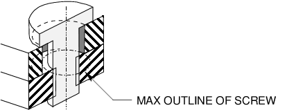
In Figure 15 , a screw is shown clamping two plates together. A tapped hole has no nominal clearance, so it cannot be located to a zero positional tolerance. The phantom line shows the maximum outline that could be occupied by the screw. The clearance hole is shown shifted the maximum acceptable distance, which means it is touching the maximum outline.
The nominal diameter of the screw is Dscr.
The fabricator can locate a hole to within a diameter of Gfab.
The fabricator can make the clearance hole to a tolerance of ±tfab.

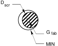
Approximately as per Figure 11 , the clearance hole is specified with MIN and MAX diameters, and it is located by a positional tolerance of zero.
In Figure 16 , the screw is shown shifted the maximum distance. The clearance hole is shown at the exact nominal position, just clearing the screw.

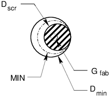
The fabricator can locate the clearance hole to within Gfab. Figure 17 shows the clearance hole shifted the maximum distance, and clearing the screw shifted the maximum distance the opposite way.
Since the hole can be fabricated to ±tfab, your maximum sized hole will be,

The values Dmin and Dmax do not show up on fabrication drawings. They are only intermediate values, used to determine MAX.
The hole must not exceed diameter MAX. The screw must pass through it. Otherwise, you do not care. The maximum error condition is shown in Figure 15 .
The zero tolerance is applied at MMB, as shown in Figure 13 .
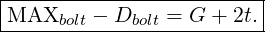
For a tapped hole of major diameter D and a maximum allowable clearance hole MAX,
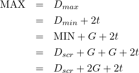
| (20) |
| (21) |
If you are the designer and you specified MMB, your error budget is
| (22) |
If you are checking drawings, the drafter will have set the geometric tolerance of the tapped hole and defined the MINscr. Your error budget for the clearance hole is

See Figure 7 .

…then you can select a slightly larger angular tolerance and recalculate the diametral tolerance…
If on a screwed pitch circle
…then you can select a slightly larger angular tolerance and recalculate the diametral tolerance…
You don’t gain much by all this calculation. If you are having problems, you should really consider datum dimensions.